
Ball Check Valve - T115AR | Zubi

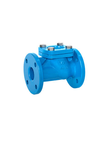
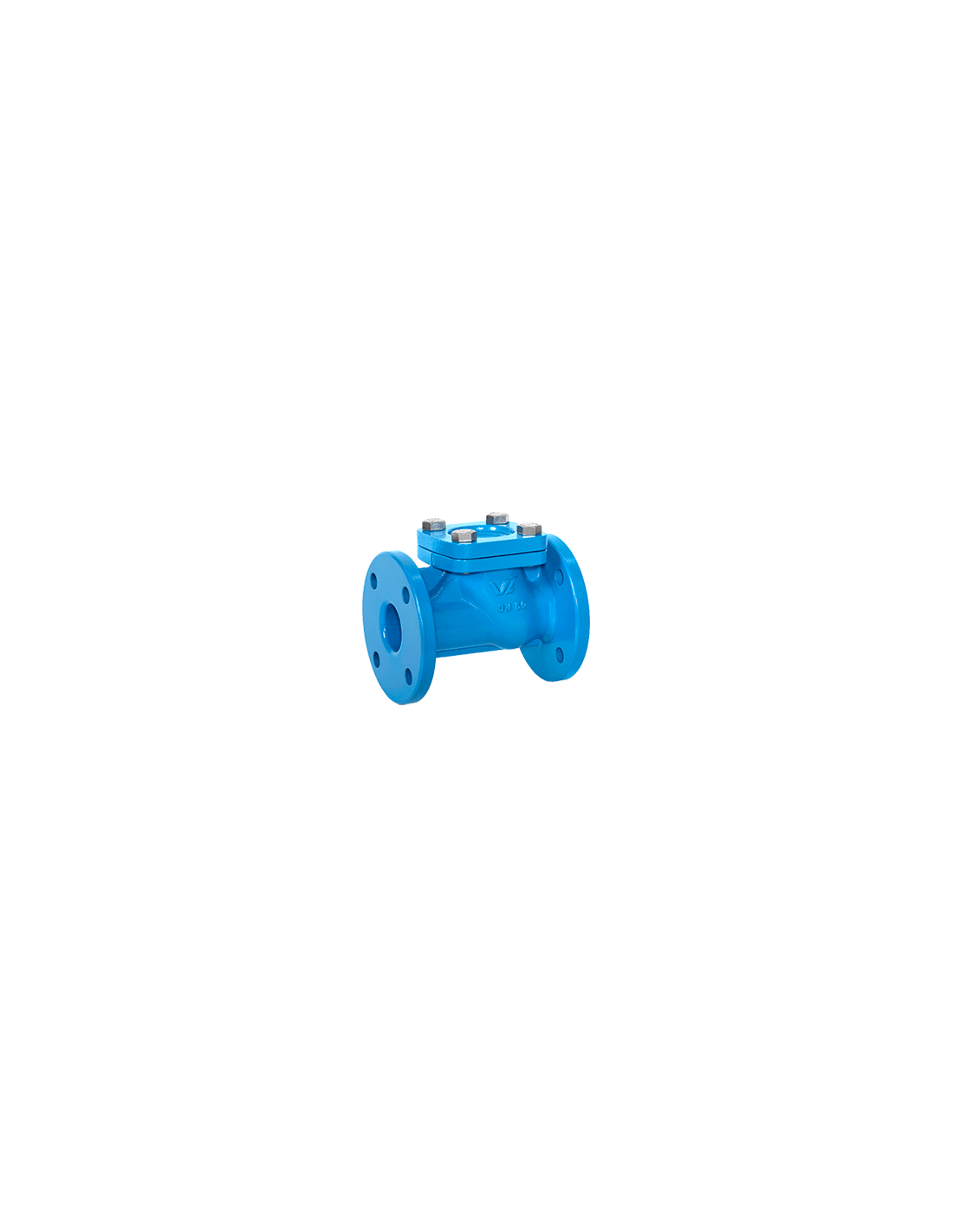
Zubi T115AR – Ball Type Non-Return Valve
The Zubi T115AR is a flanged ball check valve with a self-cleaning geometry, designed for water, wastewater, and low solids-content liquids. The ball rotates during operation, minimizing the risk of solids accumulation on the sealing surface. No actuator is required for operation.
Technical Data
- Connections: PN10 / PN16, ANSI 125 / 150
- Operating Pressure: DN20–DN125: 10 bar, DN150–DN250: 6 bar
- Minimum Opening Pressure: 0.3 bar
- Installation: horizontal, vertical, or inclined, depending on body configuration
- Body includes flow direction arrow for correct installation
Construction Materials
Body options: GG25, GGG40, GGG50, CF8M / AISI 316, CF8 / AISI 304, or special alloys on request. Internal linings available. Ball material varies by size:
- DN20–DN40: resin
- DN50–DN100: aluminium with NBR coating
- DN125–DN250: GG25 with NBR coating
Resin balls are supplied without rubber coating.
Applications
Suitable for wastewater, process water, low solids-content liquids, and pipelines requiring full bore flow without dead zones for solids accumulation. For slurry, chemicals, or seawater, verify body, lining, and ball material compatibility.
Standards / Compliance
Complies with PED 2014/68/EU (Fluid Group 1(b), 2, Category I Module A) and ATEX 2014/34/EU for Area 2 & 22.
FAQ
When is a ball check valve preferred over a swing check?
When suspended solids or risk of deposits are present in the medium.
What should be checked before selection?
DN, available differential pressure, solids concentration, body material, lining, and NBR compatibility with the process fluid.
Description
Tap to zoom