


| DGRL 2014/68/EU (PED Pressure Equipment Directive) | |
| TRB 801 Annex II No. 45 | |
| TRD 201 (Welding of components made of steel, manufacturing - inspection) | |
| AD 2000 | |
| DIN 3230 T1/T2/T3 (Technical conditions of delivery for valves) | |
| DIN EN 729-3 (Quality requirements of weldings) |

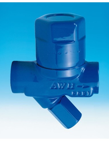
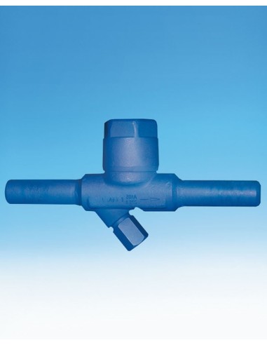
Capsule steam trap - CONA M | ARI
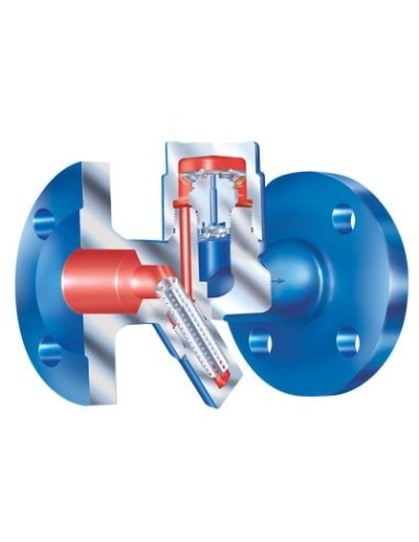
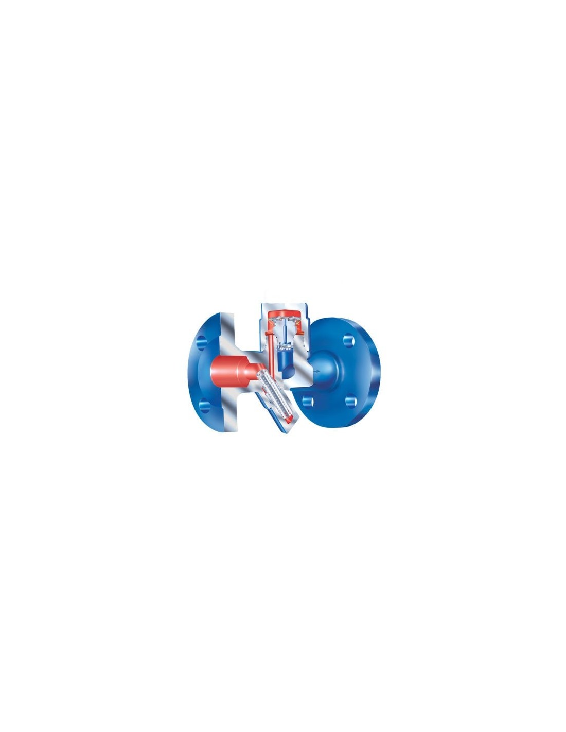
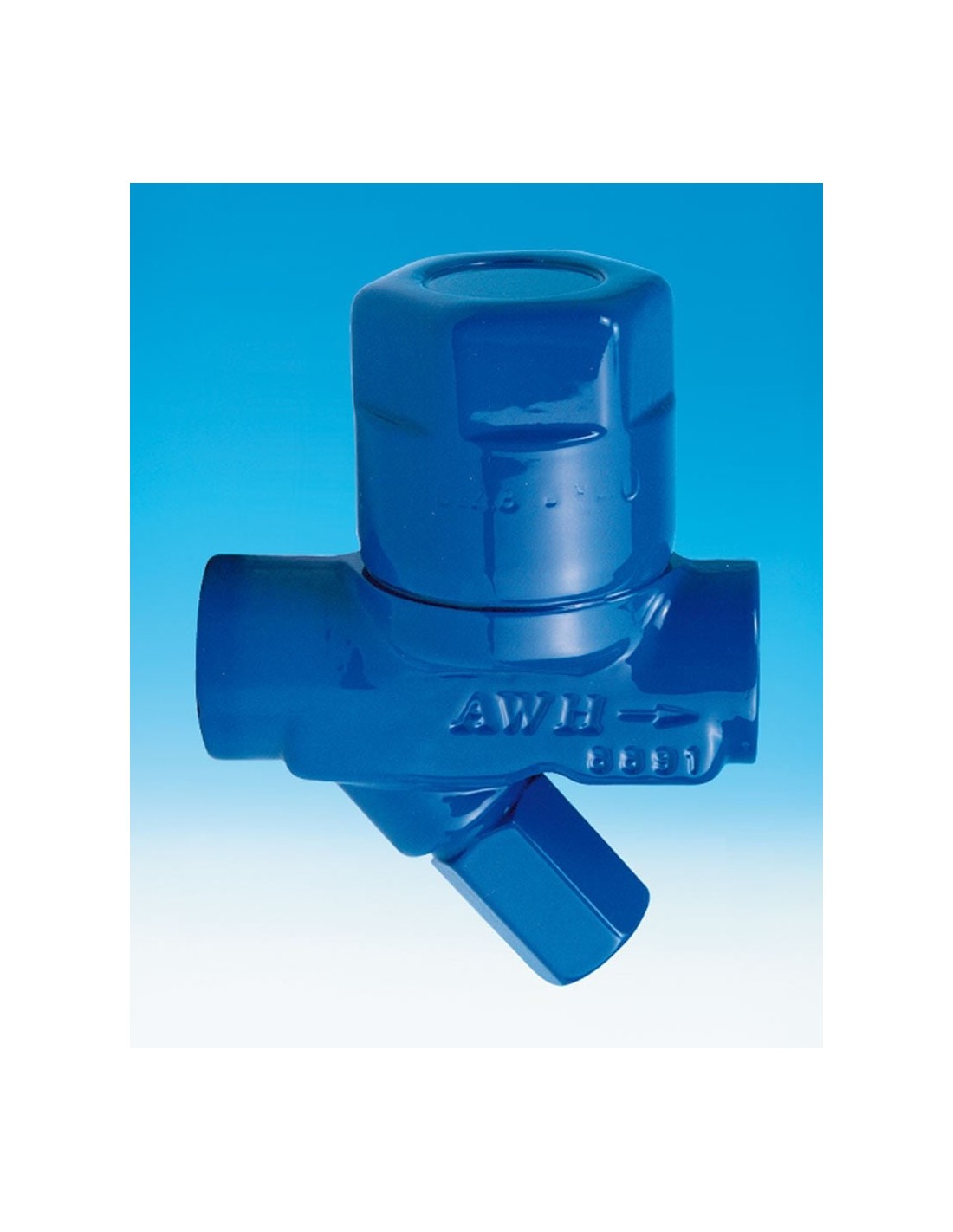
ARI CONA M – Thermostatic Capsule Steam Trap
The ARI CONA M is a thermostatic steam trap designed for draining steam in industrial installations. It operates via a membrane capsule that responds to condensate temperature and upstream pressure. It discharges subcooled condensate and automatically vents during startup and operation.
Variants and Operational Limits
- CONA M 610 PN16: Grey cast iron EN-JL1040, up to 12.8 barg and 200 °C.
- CONA M 610/612 PN40: Forged steel 1.0460 or stainless steel 1.4541, DN15–DN25, up to 22 barg and 385–400 °C depending on material.
- CONA M 611/613 PN40: Higher capacity version with increased cross-section seat.
- CONA M 616 PN40: Pilot operated / multi-capsule for very high condensate flow rates.
Thermostatic Capsules
Capsule selection determines discharge temperature:
- No. 1: Near boiling temperature, up to 5 bar inlet pressure.
- No. 2: Subcooling approximately 10 K, typical choice.
- No. 3: Subcooling approximately 30 K.
- No. 4: Subcooling approximately 40 K, mainly for low and medium pressure steam tracing.
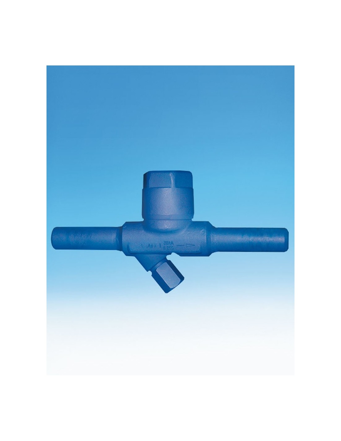
Connections and Standards
Available with flanges EN 1092-1/-2, thread Rp per EN 10226-1, NPT per ANSI B1.20.1, socket weld per EN 12760, and butt weld prepared per EN ISO 9692. Documentation includes PED 2014/68/EU, AD 2000, TRD 201, and DIN 3230.
Applications
Suitable for steam tracing, small heat exchangers, heating lines, condensate collectors, and points requiring controlled subcooling before discharge. No actuator required. Selection based on pressure, temperature, condensate flow, desired subcooling, backpressure, and body material.
Maintenance
The CONA M can be installed in any position except cover/screwed cap downwards. Before startup, check material, pressure, temperature, and flow direction. Contaminants, welding residues, or clogged filters can cause leakage or reduced flow.
Datasheet and documents
Tests and certifications
Tap to zoom