
3 Way Ball Valve - PN16 - 916 | JC
3 Way Ball Valve - PN16 - 916 | JC
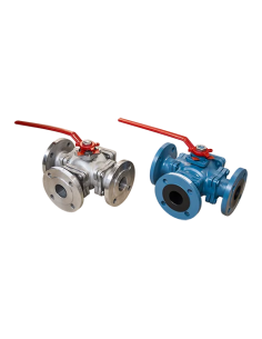
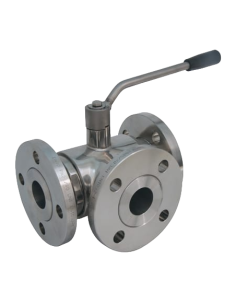
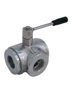
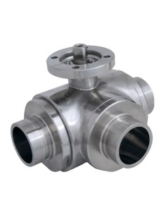
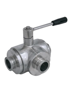
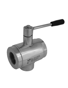
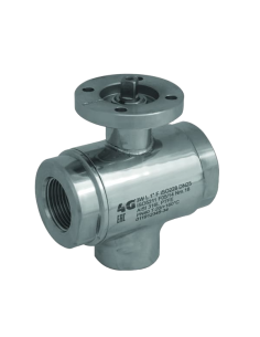
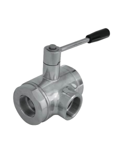
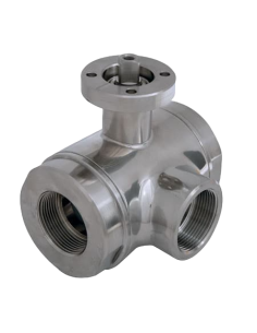
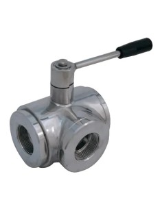
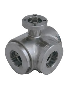
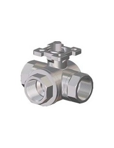
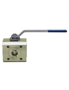
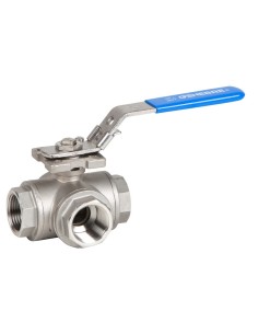
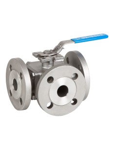
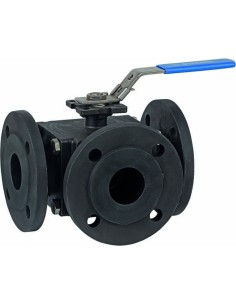
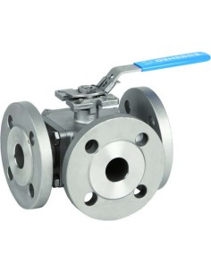
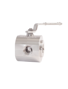
JC 916 Three-Way Ball Valve PN16, L-Port Configuration
The JC 916 is a flanged, three-way ball valve with floating ball and full bore design, intended for flow diversion between two lines via 90° rotation. The L-port configuration is used where a common line must be alternately connected to two branches without mixing. Available in DN25–DN200, PN16, with...