Μειωτής Πίεσης Πιλότου Miyawaki τύπος RE10N | Φιλιππόπουλος α.ε.

Μειωτής Πίεσης Πιλότου Miyawaki τύπος RE10N

Miyawaki RE10N μειωτής πίεσης πιλότου για ατμό

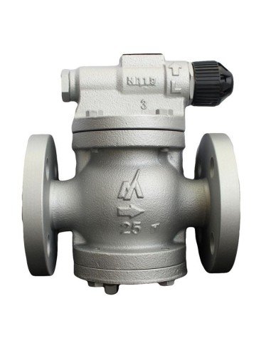
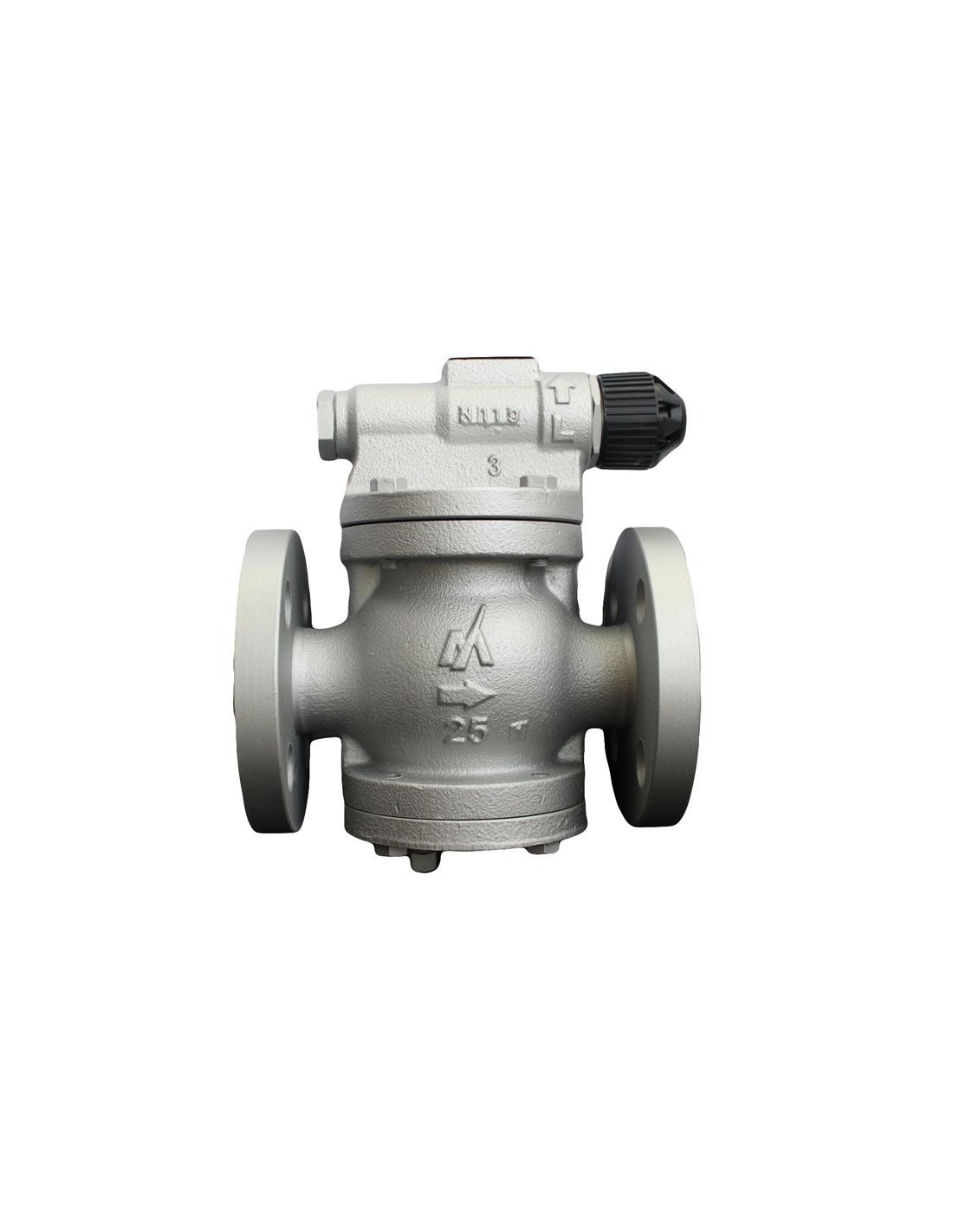
Ο Miyawaki RE10N είναι πιλοτικά ελεγχόμενος μειωτής πίεσης για ατμό, σε συμπαγή φλαντζωτή κατασκευή. Η πίεση από τον θάλαμο πιλότου οδηγεί το τμήμα κίνησης και μεταβάλλει το άνοιγμα της κύριας βαλβίδας, ώστε η downstream πίεση να διατηρείται στο ρυθμισμένο set point. Η ρύθμιση γίνεται χειροκίνητα από λαβή με μηχανισμό ασφάλισης.

Τεχνικά χαρακτηριστικά

  • Μεγέθη: 1/2” έως 2”.
  • Σύνδεση: φλαντζωτή FF/RF.
  • Πρότυπα φλαντζών: JIS 10K, 16K, 20K.
  • Μέγιστη πίεση λειτουργίας: 1,6 MPa.
  • Πίεση εισόδου: 0,1–1,6 MPa.
  • Ρύθμιση πίεσης εξόδου: 0,034–1,2 MPa.
  • Kvs: 0,9–13,8 m³/h.
  • Μέγιστος λόγος μείωσης πίεσης: 20:1.
  • Μέγιστη θερμοκρασία λειτουργίας: 220°C.
  • Υλικό σώματος: ductile cast iron FCD450.
  • Ελάχιστη διαφορική πίεση: 0,07 MPa.
  • Lock-up pressure: έως 0,03 MPa.

Κατασκευή και λειτουργική συμπεριφορά

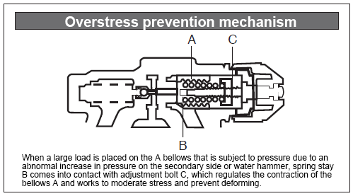
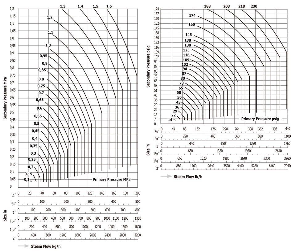
Ο RE10N διαθέτει ενσωματωμένο φίλτρο και μηχανισμό προστασίας από υπερφόρτιση. Η ελάχιστη ρυθμιζόμενη παροχή είναι 5% της ονομαστικής παροχής, στοιχείο σημαντικό για επιλογή σε μεταβαλλόμενο φορτίο ατμού. Η επιλογή μεγέθους γίνεται από capacity chart, με p1, p2 και απαιτούμενη παροχή kg/h.

Εφαρμογές

Κατάλληλος για τοπική μείωση πίεσης ατμού σε εξοπλισμό τροφίμων, βαφεία, καθαριστικές διατάξεις, θερμαντικά στοιχεία και HVAC καταναλωτές. Η φλαντζωτή σύνδεση τον διαφοροποιεί από τον RE3, ο οποίος καλύπτει αντίστοιχες πιέσεις αλλά σε σπειρωτή εκτέλεση.

Εγκατάσταση

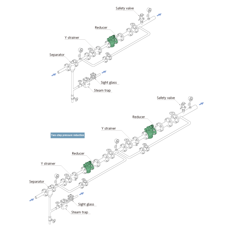
Η τυπική διάταξη περιλαμβάνει Y-strainer, separator, ατμοπαγίδα, μανόμετρα εισόδου/εξόδου, βάνες απομόνωσης και bypass συντήρησης. Για λόγο μείωσης πάνω από 20:1 πρέπει να εξετάζεται διβάθμια μείωση πίεσης.

Τυποποίηση (Επιλογές)
  • JIS
Σύνδεση (Επιλογές)
  • Φλαντζωτή
Υλικό Κατασκευής (Επιλογές)
  • Ductile Cast Iron
Ονομαστική Πίεση (Επιλογές)
  • 10K
  • 16K
  • 20K

Περιγραφή

Features

Pressure reducing valves for steam

These are automatic valves that reduce the steam supply pressure to the certified pressure for the device in use, and keep it steady.

Compact and cost effective design

It has a space saving (ultra small/lightweight). Low heat dissipation with superb energy saving properties and cost performance.

Superb durability

Offers superb durability thanks to an overstress prevention mechanism.

Built-in strainer

Pilot operated valves

The drive section detects the pressure supplied from the pilot chamber, and the degree of opening of the valve is adjusted to keep the pressure on the secondary side at a set level.

Simple pressure adjustment

Pressure adjustment can be performed by hand using a handle, with no tools required. (with lock mechanism)

Easy maintenance

It is easy disassembly and reassembly.

RE10N_kikou

Uses

Suitable for a wide range of uses including devices for foodstuffs, dyeing, and cleaning as well as heating equipment and air conditioning equipment.

Dimensions/Weight

RE10N_FF
SizeDimensions (mm)Dimensions (in)Weight
LL1H1H2WLL1H1H2W(kg)(lb)
1/2”160175133801006.36.95.23.13.97,115.7
3/4”7,416.3
1”1701806.77.18,518.7
1 1/4”2002101541031307.98.36.14.15.114,231.3
1 1/2”14,331.5
2”2202208.78.715,634.4

Specifications

ModelConnection

Max. operating

pressure

Operating pressure

range

Control pressure

range

Values

Max.

pressure

reduction ratio

Max. operating

temperature

Body

material

TypeSize(MPa)(psig)

Primary side

pressure

(MPa)

Primary side

pressure

(psig)

Secondary side

pressure

(MPa)

Secondary side

pressure

(psig)

CvKvs(℃)(℉)
RE10N

Flanged

FF,RF*

1/2”1,62320,1 - 1,614.5 - 2300,034 - 1,24.9 - 1741,00,920:1220428

Ductile cast

iron

FCD450

3/4”2,52,2
1”4,03,4
1 1/4”6,55,6
1 1/2”9,07,7
2”16,013,8

*Can potentially meet these flange standards: JIS 10K, 16K, 20K

● Offset: up to 0,03MPa (4.4psig)

● Minimum differential pressure: 0,07MPa (10.2psig)

● Minimum adjustable flow rate: 5% of the rated flow rate

● Lockup pressure: 0,03MPa (4.4psig) or lower

Capacity Chart

RE10N

● How to use selection chart (example)

To reduce the pressure of 800kg/h (1764lb/h) of steam from 0,8MPa to 0,5MPa (116psig to 73psig)

1. Find the point at which the primary side pressure 0,8MPa (116psig) curve and secondary side pressure 0,5MPa (73psig) horizontal line intersect.

2. Trace a vertical line from the point where they intersect, and look for the smallest-sized product where the steam flow rate is 800kg/h (1764lb/h) or more at the point where the vertical line you have traced intersects the horizontal size lines.

3. In this case, the pressure reducing valve with a size of 1 1/2” is optimum

Installation Examples

RE10N_haikan4

■Related Products Models for reference

    Sight glass TS1 T3    T3

    Y strainer YSF

    Separator   H3  H5

    Steam trap Differs depending on conditions