Indicator & Alarm Unit - Type 40A48-96 | Gefran | Philippopoulos s.a.

Indicator & Alarm Unit - Type 40A48-96 | Gefran

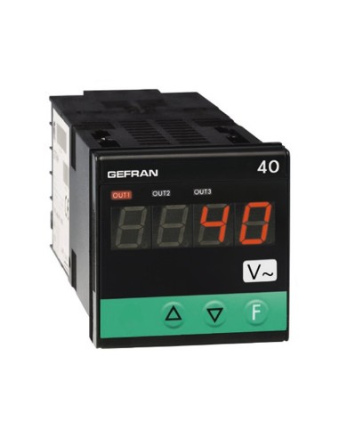
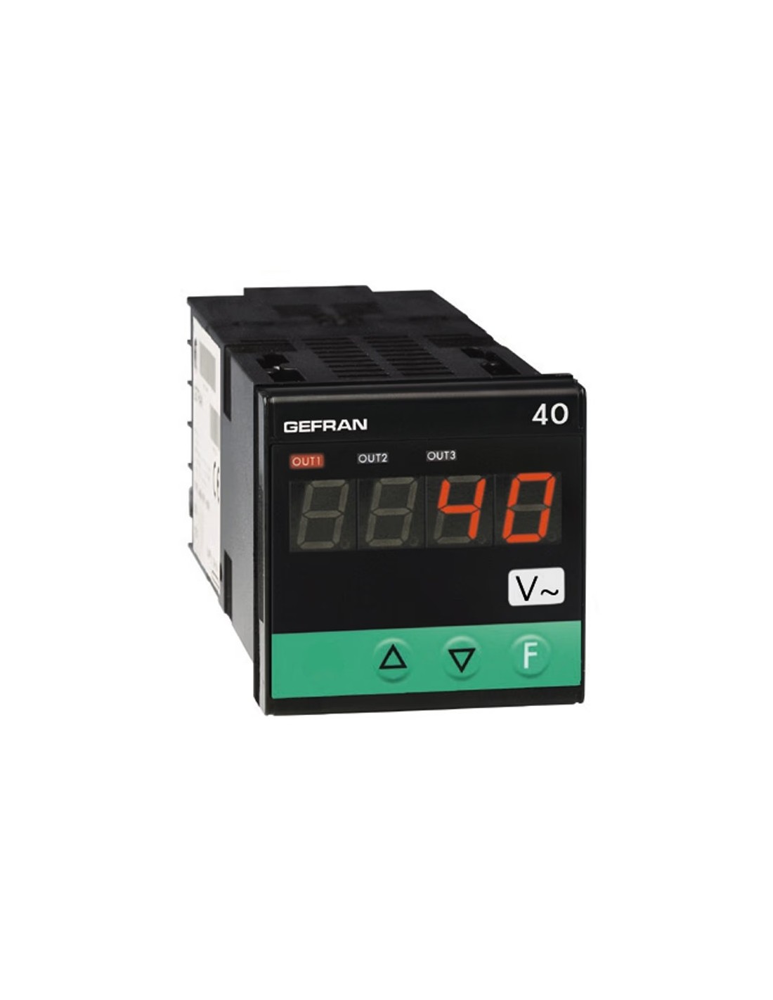
Gefran 40A 48 / 40A 96 Indication & Alarm Unit

The Gefran 40A 48/96 is an industrial panel-mounted indication and alarm unit designed for direct measurement of AC voltage or AC current in automation panels. It is not a PID controller; its primary functions are true RMS display of sinusoidal signals, alarm threshold monitoring, and signal retransmission. Available in 48×48 mm (1/16 DIN) and 96×48 mm (1/8 DIN) formats, the unit features an IP65-rated front panel and three control keys.

Measurement Inputs

Scale selection is performed via the front panel and terminal configuration, without the need for external shunts or adapters. Supported input ranges:

  • AC Voltage: 0–2, 0–20, 0–200, 0–500 Vac
  • AC Current: 0–20, 0–50, 0–200 mAac; 0–1, 0–5 Aac

Display range is configurable from -1999 to 9999 (4-digit models) or -999 to 999 (3-digit models).

Alarm Outputs & Signal Retransmission

Up to three outputs are available: relay (5 A / 250 Vac) or logic output (6 V / 20 mA). The 96×48 mm model also offers a triac output (20–240 Vac, 3 A) as an alternative to relay contacts. Optional 4–20 mA retransmission (Rmax 150 Ω) is provided for integration with PLCs, recorders, or secondary indicators.

Digital Input & Alarm Functions

The isolated digital input (24 Vdc / 4 mA) supports reset, hold, flash, peak handling, or release of latched alarms. Alarm setpoints can be configured as absolute, deviation, or symmetrical deviation, with adjustable hysteresis, startup masking, and on/off delays.

Typical Applications

  • Load current indication for resistive heaters, motors, or power lines
  • AC voltage monitoring in machine panels
  • Overcurrent/undercurrent alarm signaling
  • 4–20 mA retransmission to PLC or SCADA systems
  • Test benches and production lines requiring local electrical measurement

Operating Conditions & Standards

Power supply: 100–240 Vac/dc or low-voltage variants. Operating temperature: 0–50 °C; storage: -20–70 °C; humidity: 20–85% RH non-condensing. Installation category II, pollution degree 2. CE marked for EMC (2014/30/EU, EN 61326-1) and LVD (2014/35/EU, EN 61010-1).

Description

Technical specifications

Overview

Microprocessor based indicator in both 48×48 (1/16 DIN) and 96×48 (1/8 DIN) formats manufactured with SMT.

The instruments have a lexan membrane faceplate (guaranteed to IP65) which has 3 keys, a 3 digit display for the 48×48 format and a 3 / 4 digit display for the 96×48 format, and 3 indicating LED's for the output statuses.

The input signal section provides for the visualisation of the sinusoidal effective value corresponding to following signals:

  • AC voltage: 0 to 2, 0 to 20, 0 to 200 and 0 to 500Vac
  • AC current: 0 to 20, 0 to 50, 0 to 200mAac 0 to 1, 0 to 5Aac

The selection is made using the faceplate keys and correct input terminals.

No external shunt or adapter is required.

A digital input (24Vdc/4mA) is available for resetting, hold, flash, peak handling or releasing latch.

The instruments have a maximum of 3 outputs that can be mechanical relays (5A/250V) or logic outputs (0 to 11Vdc).

One output of 4 to 20mA (max. 150W) is available for retransmitting the measured input signal.

The retransmission output, the digital input and the third output are alternatives in the 48×48 format, all these options are available contemporaneously in the 96×48 format.

Finally, a triac can be fitted (as an alternative to the other two relay outputs) to drive resistive loads up to a maximum of 2,5A at 220V.

The programming of the instrument is made easy by grouping the parameters in function blocks (CFG for the alarm hysteresis, Inp for the inputs, Out for the outputs…) and by a simplified data entry menu.

The configuration can be simplified even further using the PC programming kit made up of a connection cable and a menu guide program that runs under Windows (see data sheet cod. 80021).

A configurable personal software protection code (password protection) can be used to restrict the levels of editing and displaying the configuration parameters.

Description

  • AC voltage, AC current direct input on instrument terminals
  • Protected code configurable from keypad
  • 4 to 20mA retransmitted output
  • Up to 3 relay outputs
  • Configurable by serial link
  • Labels to customize measured physical unit

Certifications