
Flow control valves
Water flow control valves are used in water supply networks, pump stations, reservoir inlet lines, distribution zones, and industrial hydraulic circuits where flow must be limited or maintained at a defined value despite pressure variation. Selection should be based on the required flow setpoint, available differential pressure, minimum pilot operating pressure, head loss, installation position, and the dynamic response of the piping system.
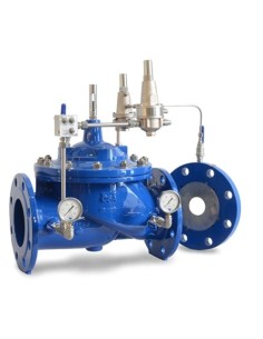
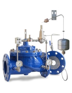
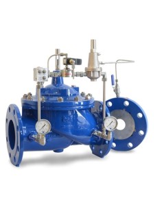
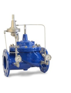
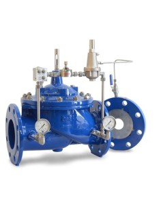
This category includes CSA XLC 330/430, 331/431, 334/434, 335/435, and 380/480 automatic hydraulically operated control valves, with globe-pattern body, EN 1092-2 flanged ends, and design/testing in accordance with EN 1074. Body and cover are ductile cast iron GJS 450-10; the control circuit is stainless steel, and the seat is stainless steel. Available pressure classes are PN 10, PN 16, and PN 25. Standard operating conditions are for treated water up to 70 °C, with minimum pilot pressure of 1.2 or 1.5 bar depending on model.
The XLC 330/430 limits flow to a preset value by means of an orifice plate assembly and pilot control, while remaining fully open when actual flow is below the setpoint. The XLC 331/431 combines maximum flow limitation with downstream pressure reducing and regulating functions, for use on pumping mains, secondary pressure zones, and over-flow protection duties.
The XLC 334/434 combines minimum/maximum tank level control with maximum flow limitation during filling. The XLC 335/435 adds solenoid actuation for remote opening or closing on signal, used for alarm logic, emergency shut-off, or supply isolation. The XLC 380/480 operates as an excess flow valve: it remains open below the setpoint and closes fully when sudden flow exceedance is detected, with manual reset after trip.
Maintenance should include inspection of the orifice plate, pilot lines, needle valves, flow stabilizers, strainers, diaphragm, seat, position indicator, and actual trip or limiting flow. Suspended solids, trapped air, or incorrect sizing can cause hunting, delayed response, unstable regulation, or insufficient flow limitation. Leakage assessment should consider seat condition, pilot circuit cleanliness, and diaphragm integrity.